The Goal
To turn this wonderful map visualisation by Jamie Whyte into a real physical object using 3D printing.
Additional Goal
To create a simple online converter that can convert from GeoJson to STL, making it much easier for people to print their own map data. Feel free to check it out at geojson-to-stl or help me improve it at github
stages of development
I approach all projects by breaking them down into stages, addressing single areas of development at a time instead of tackling the project as a whole.
Understanding the data
Geographic Coordinates to Cartesian Coordinates
Cartesian Coordinates TO STL
Tolerance
Understanding the data
First I look at what I have, a GeoJson file.
The GeoJson may at first be overwhelming but it is well organised in the JSON format. Amazing diagrams that explain the structure here and great online tools to make the format more readable using indentation here.
With no knowledge of GeoJson but strong familiarity with JSON I can see that we have an object with a huge list of features, 215 to be precise, I imagine each one is a ward by looking at the first item that is expanded a little.
The geometry object looks very useful, lets expand it …
Ok it looks like the geometry object is a long list of coordinates. Looking a little closer we can see that the first and last coordinate is the same, so we have a list of 2D coordinates that loop round to form a complete shape (a polygon as the type specifies in the file). Fantastic we can use these coordinates to generate our STL files somehow just need to convert these coordinates (known as Geographic coordinates) to X,Y coordinates (known as Cartesian coordinates).
Geographic Coordinates to Cartesian Coordinates
I had a look around for how to convert Geographic to Cartesian coordinates and found this page from Wolfram MathWorld. I needed to map the sphere to a cylinder and then roll it out, this is achived using this formula to convert the values;
X = λ - λ₀
Y = tan(θ)
where λ is longitude and θ is latitude
λ₀ is our first longitude point making x relative to our first point however Y is currently relative to the equator which will distort our model so we need to subtract tan(θ₀) to also make Y relative to my first point. This results in:
X = λ - λ₀
Y = tan(θ) - tan(θ₀)
Cartesian Coordinates TO STL
I now have a list of X,Y points, I now need to understand the STL format to generate a correct file that Cura can understand and recreate my shape. There are 2 formats STL can be, in ASCII or Binary. Given Binary’s only advantage is smaller file size, I picked ASCII as it is just plain text, making it much easier to find errors when things are not working correctly.
To make a shape I need to start my file with
solid name (name can be any whatever I want)
and end it with
endsolid name (name has to be the same as used at the start)
Computers are very dumb but they can do the same thing very fast this results in almost all 3D computer graphics being stored as a huge number of triangles, as any shape can be broken down into a number of triangles to represent that object.
STL defines a triangle in this format :
facet normal ni nj nk
    outer loop
        vertex v1x v1y v1z
        vertex v2x v2y v2z
        vertex v3x v3y v3z
    endloop
endfacet
I turned out that I could break the shape down into rectangles. As I walked around the shape I take my current point and next point to determine the width of the rectangle, then the height will be determined by a constant value. These rectangles can then be split into 2 triangles by cutting through 2 diagonal points.
The STL format for the method above
facet normal 0 0 0
    outer loop
        vertex point1X point1Y 0
        vertex point1X point1Y 0
        vertex point2X pointY2 height
    endloop
endfacet
and
facet normal 0 0 0
    outer loop
        vertex point1X point1Y height
        vertex point2X point1Y height
        vertex point2X point1Y 0
    endloop
endfacet
The facet normal is a bit more complicated to explain, without getting mathsy, but thankfully after reading about it and testing it in Cura we can safely ignore it and just put facet normal 0 0 0. **Note this is bad practice and will not load in some STL viewers that are more strict than Cura.
I loaded the file into Cura to see a complete shape!!

Fantastic we have the perimeter done!! turns out we don’t need a top and bottom face for Cura to generate the printing code, so I printed the piece.
Beautiful! Almost perfect except for the curling of the edges, I tweaked some setting in the later prints to help reduce this. However I had another worry… Would they fit together, some of these angles are really small so I tested it by printing out an area… Rochdale wards have some interesting interlinks (also doubles as my home town) so I printed Rochdale.
Tolerance
A wonderful print, with less curling this time!! However my worry was correct two of the pieces will not fit together! This is due to the plastic having a thickness and the points have no gap to account for this, we need to add some tolerance. How much tolerance was worked out later with some trial and error later but for I needed a way to compute all the new X,Y points with tolerance applied first.

My plan was to move each point into the shape by a set amount (tolerance). The tricky part was to move the point in the correct direction. Originally, I started out by using a lot of trigonometry and calculating way to many angles (with many conditions) to work out what the correct angle was, then calculate the line. Until I found this answer on a stack exchange site…
"By definition, the sum of two vectors is equal to the diagonal of the parallelogram spanned by the vectors."
I did however have to draw out what the person was saying to understand what he meant.

We get 2 vectors (lines) from a point of the same length ( I can normalise any vector so this is easy enough). I then stick the opposite vector to the end of the other vector and to get a parallelogram

Draw a line from our point to the opposite point and we have a line with a direction exactly half the angle! Now all that is left to be done is to walk along the line by the threshold amount to get my new X,Y coordinates for that point.

There is however 1 flaw in this method, it only ever dissect the smaller angle of the 2 possible angles, however there are times I needed the larger angle (orange angle) but if I followed the green line then I would have gone in the wrong direction… Thanks to all the trigonometry I did earlier I had a nice method to calculate if i want the convex (large) or concave (small) side, telling me which direction to go in.
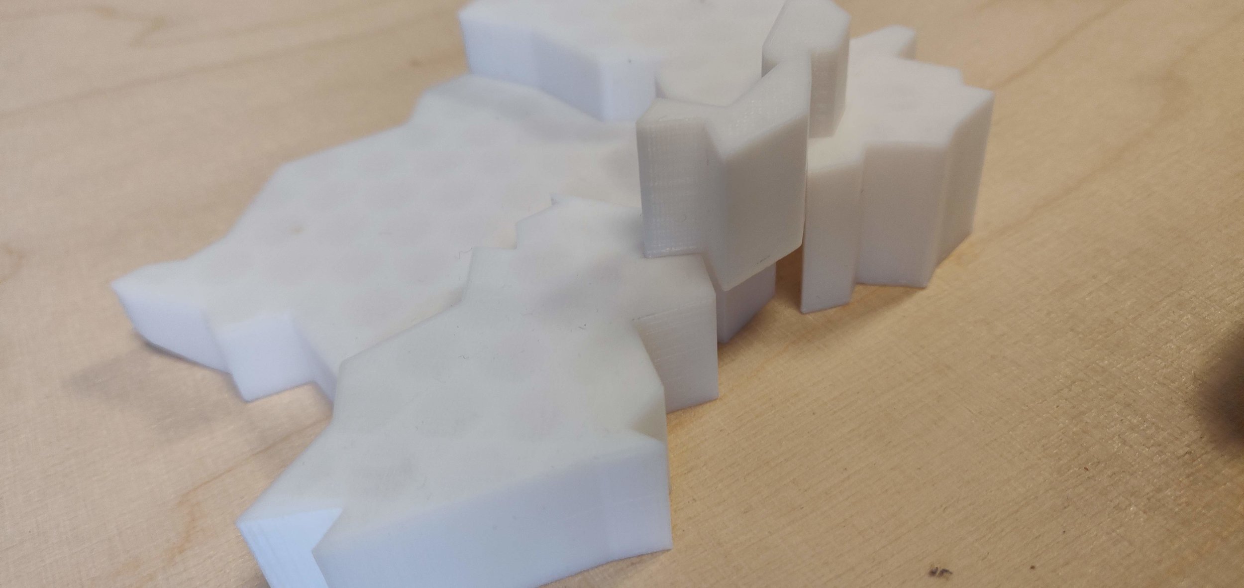
The obvious next question is what tolerance I should give the print I went down the simple route of printing out a very thin version (to make it a quick print) of the 2 pieces that wouldn’t fit together first with 0.1 then 0.2 and finally 0.3 millimetre tolerance.

left to right 0.1 mm, 0.2 mm and 0.3 mm tolerance.
The 0.1mm didn’t fit at all you can even kind of see that the bigger cut out doesn’t even fit together. 0.2mm could fit with some squeezing but was very eager to pop itself back out, whereas the 0.3mm fit really nicely… So 0.3mm it is!
Everything is sorted and ready for the whole map now, stared with Rochdale to triple check everything worked and then continued on with the rest of the map
Images of the Rochdale area this time in the correct colours and with the tolerance applied, we can see the pieces fit together perfectly!
Reflections
This was a great project (even if it was over a week of non stop printing) I’ve been overwhelmed by the reaction it has received. There are a lot of extra improvements that I can think of making, but for a while now I’m going to make the online converter work better and be more user friendly.
One last note I need to thank TIH for letting me use their printer, especially for 2 weeks of nearly constant use!
I have also added a dead ends section bellow to highlight that there was a few things that I spent a while on that was either just not used or made no impact on the end product. The section is there to show that dead ends is just a normal part of development and that they do usually provide something useful, be that increased knowledge in the area or a nicer product at the end.
Dead ends - rabbit holes (quick notes)
Using direction and magnitude to create the shape
Originally I was working out the parimeter from just calculating the distance and direction from point to point, using the functions from this amazing site https://www.movable-type.co.uk/scripts/latlong.html

I did this knowing that it may be off a little because you cannot map a sphere very easily to a flat 2D plane. However I never knew that I would be so far by my guess I was about 1KM (on my scale 1cm) out after spending an hour or so making sure I was definitely moving in the correct direction at every point.
I couldn’t believe just how far out it was I expected me to be less than a mm off and I would just snap the ends together somehow so it was a complete object. However after seeing the gap it left I knew I had to do it the proper way.
Polygon triangulation
(loved the name but basically I’m putting a surface on the top and bottom of my shapes)
As mentioned earlier when i first created the perimeter of the shape, I didn’t think Cura would add the top and base to complete the shape allowing it to print, apparently the older versions didn’t but i couldn’t find any word of it in the changelog.
So I ended up spending a whole day making this work, after some googling I found the name for it was called “Polygon triangulation” and found that the easiest algorithm to implement was probably ear clipping admittedly this was really fun to implement, a great YouTube video to visualise how it works here. Even though it wasn’t needed I shall still be using it with my online conversion tool because it makes the models look significantly better when rendering, despite it making no difference in the print.